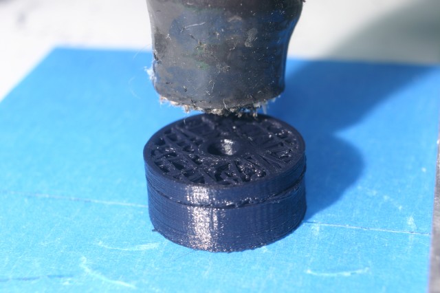
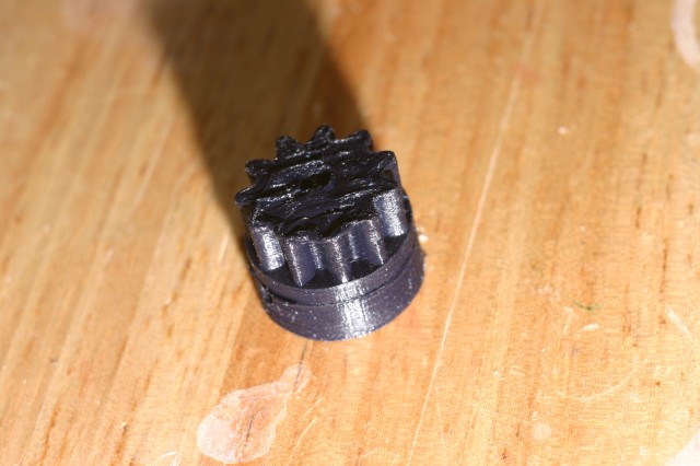
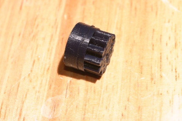
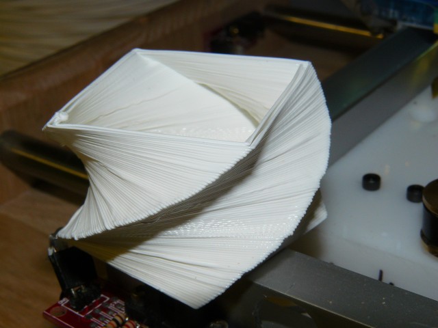
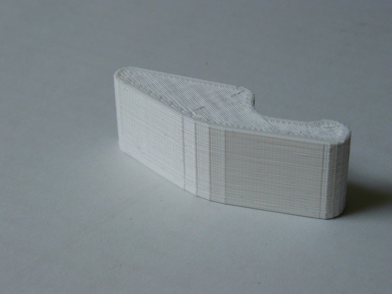
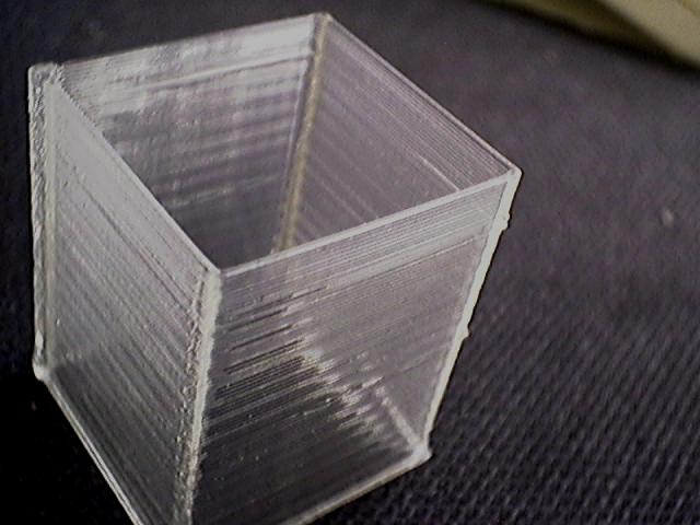
I did a test print at 0.08mm layers, the smallest layer height I’ve attempted yet.
I used a Makergear Plastruder, and black Ultimachine 4043D PLA.
Skeinforge sliced it onto 187 layers. It was not a fast print, taking about 2.5 hours.
Aside from a kind of smeary top layer, it came out ok.
Pictures follow:
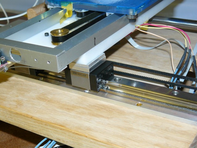
I’ve replaced my X axis, which was bronze bushings sliding on steel rod, with a recirculating-ball linear bearings and guide. The former X axis had enough play in it that you could feel it just by wiggling the print bed, and was affecting print quality quite a bit.
Between my new extruder hot-end, this new bearing, and lowering layer height to 0.36mm, I’m getting print quality that’s better than anything I’ve produced to date.
It’s also faster, so much faster that I’ve had the motor miss a few steps. I’m experimenting with feeding 24 volt power to the stepper motor drivers, and initial results seem good, although everything runs a bit warmer. I also have another linear bearing, and may use it on the Y axis.
Here’s a “before” picture of my previous X axis slide:
And here’s a picture of the new linear bearing & rail:
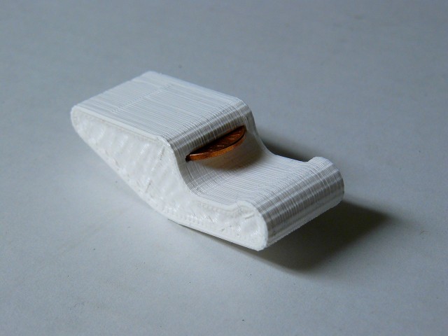
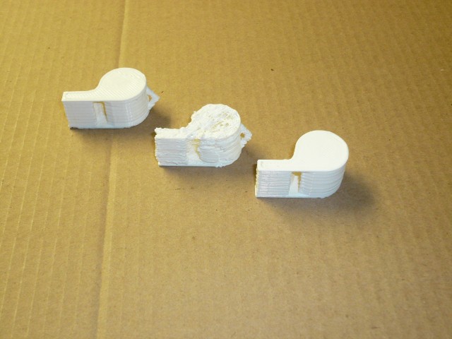
Here’s some of the first test prints I did with the new bearing:
Here is some video of it in action, if you listen carefully you can hear the *tick* *tick* *tick* *tick* of the ball-bearings clicking around their recirculating channels inside the carriage.
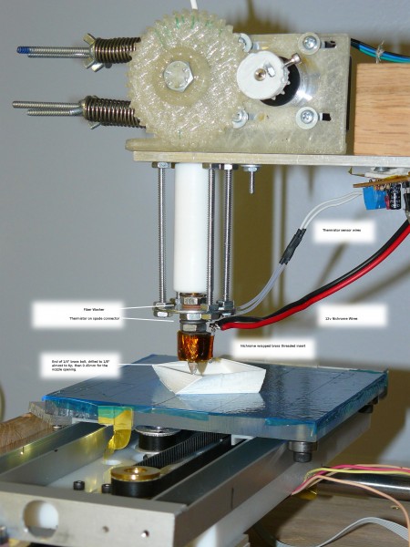
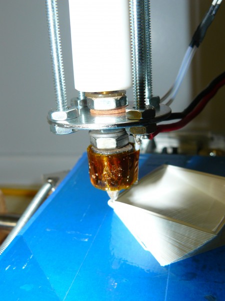
After melting the PTFE insulator yet another time, I’ve built another hot end. This one doesn’t use the PTFE as a stress-bearing part, but only to contain any plastic that may ooze above the top of the heater barrel.
The heater barrel is threaded into the PTFE about 0.25″, just enough to keep it aligned. The PTFE isn’t attached anywhere else, just sandwiched between the washer and the aluminum mounting plate above it.
I also made modular heater and thermistor, ala Makergear.com HeatCore. (I know a good idea when I steal it).
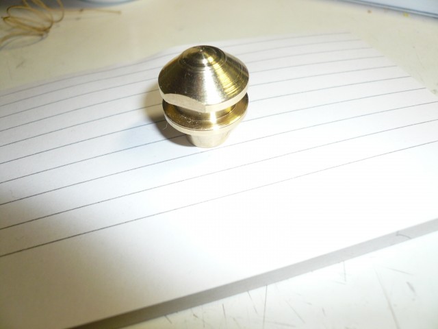
I’ve also ditched the separate nozzle, and used the brass screw as a one-part barrel+nozzle. The opening was drilled with a 0.45mm drill.
Print quality has improved by a lot, and I haven’t had any problems with the feed pinch-wheel teeth stripping the filament.
After trying to do some printing with a spool of White PLA 4042D, and being unable to replicate the quality level I’d got with Natural PLA 4042D, I started to look for possible differences in the composition of the filament.
After reading the datasheets, the only documented difference is %2-%4 pigment. I’d had decent results with green & black PLA, so I wasn’t convinced that the pigment was a factor. (Although at this point I was so frustrated that I wasn’t ruling it out, either).
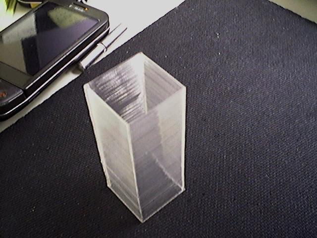
I’ve printed so many single walled squares that I’m seeing them in my sleep.
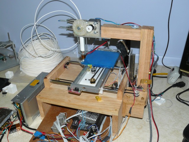
The RepRap is a 3D printer that builds small objects out of plastics, by squirting layers of melted plastic out of a nozzle, on to a computer-controlled moving platform. Once a single layer is made, it moves to the next layer up from the bottom, repeating this process until your object is created.
This process is called “Fused Deposition Modeling”, or “Fused Filament Fabrication”.
The end result is a strong plastic part, with a slightly ridged surface.
This is basically the same method used by the Stratasys FDM rapid prototyping machine, which costs around $30,000.
The Chicken & Egg problem of building a RepRap machine is that many of the parts are actually made using a RepRap, so if you don’t already have access to one, you’re at a disadvantage.
I’ve been working on what’s called a RepStrap, that is, it’s not exactly following the plans for a RepRap machine, but can be used to ‘bootstrap’ construction of a RepRap. The end result is the same in that you have a 3D printer, but the construction plans & materials differ.
When starting my build I had a few design goals: appearance, cost, and functionality.
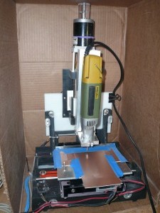
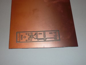
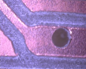
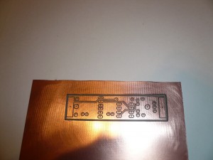
Last week I did a test pcb milling on my cnc pcb mill. I’m still learning how to properly configure the PCB-Gcode software, and I think this is the best result to date.
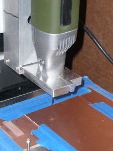
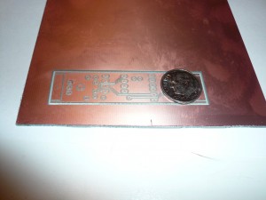
The board is the top side of LadyAda’s Drawdio board, and it took about 15 minutes to mill. I used a 60 degree pcb bit I got from a Chinese seller on eBay. Before drilling the holes I ran through the drilling gcode, once with the pcb bit still in the spindle, at a higher depth. Basicialy this drills shallow pilot holes through the copper, but not through the PCB. This helps reduce the amount of “walking” that the tiny drill bit does when it’s drilling the holes.
The holes are still off-center a bit from the pads, I’m still trying to figure out why that is. One possibility is that I accidentally twisted the router in it’s mounting when I changed from the pcb bit to the drill bit.
One more picture, after a little cleanup with some 1500 grit sandpaper, I think it came out pretty well.
