The RepRap is a 3D printer that builds small objects out of plastics, by squirting layers of melted plastic out of a nozzle, on to a computer-controlled moving platform. Once a single layer is made, it moves to the next layer up from the bottom, repeating this process until your object is created.
This process is called “Fused Deposition Modeling”, or “Fused Filament Fabrication”.
The end result is a strong plastic part, with a slightly ridged surface.
This is basically the same method used by the Stratasys FDM rapid prototyping machine, which costs around $30,000.
The Chicken & Egg problem of building a RepRap machine is that many of the parts are actually made using a RepRap, so if you don’t already have access to one, you’re at a disadvantage.
I’ve been working on what’s called a RepStrap, that is, it’s not exactly following the plans for a RepRap machine, but can be used to ‘bootstrap’ construction of a RepRap. The end result is the same in that you have a 3D printer, but the construction plans & materials differ.
When starting my build I had a few design goals: appearance, cost, and functionality.
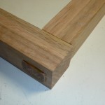
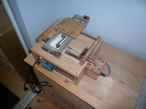
I wanted to have a finished machine that was pleasing to the eye, and looked like it belonged in the house, and not in the garage. I’ve chosen to build the main structure out of red oak, for it’s strength and appearance, and the fact that it was readily available. Woodworking is not my strength, so construction was slow & difficult. The main base of the machine is a box, which will contain the power supply and electronics.
To keep the cost under control, I’ve used mostly materials that I already had, only the wood and a few electronic parts were purchased specifically for this project.
In terms of functionality, I’ve attempted to make everything I can adjustable, to allow for small adjustments during the “dialing it in” process that I’ll do once it’s “done”.
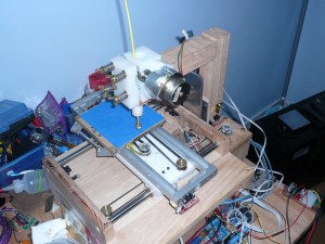
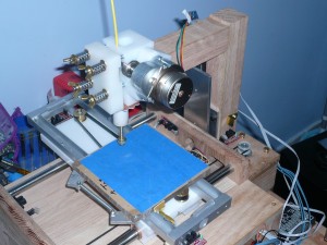
Construction is not finished, but is to the point where I have working X, Y and Z axes. The remaining work is mostly centered around the plastic extrusion head, and software setup.
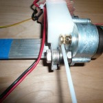
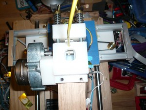
The extrusion head is a fairly touchy system, and seems to be the area where most people have to do a lot of fine tuning before getting the results they’re after. The extrusion head also has the biggest impact on output speed and the finish quality of printed parts.
I am currently on the second revision of the extruder head, my first try had problems gripping the feedstock.
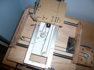
My 3 axes are using 3 different bearing mechanisms, the “X” axis is oil-impregnated bronze bushings and teflon plastic, sliding on two steel rods.
The “Y” axis is a McWire type sliding carriage that slides on aluminum channel stock, stabilized by bearings. The bearings for the “Y” are salvaged from DLT computer backup tapes that were decommissioned at work. (protip: Cutting the whole tape in half with a Sawzall is an effective data destruction method).
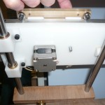
The “Z” axis is sliding on a commercially made linear bearing rail/carriage that I’d got on eBay some time ago.
There is only a single “Z” linear bearing, but since the forces it will have to withstand are pretty low, it’s rigid enough. A machine that endured greater forces, like a milling machine, would require more strength in the Z axis.
The “X” and “Y” axes are driven by 1.8 degree stepper motors with pulleys and belts, this allows for very rapid movements.
The “Z” axis is driven by a 12-TPI acme screw, which is much slower, but provides the greater torque required to lift the weight of the extruder head and it’s support-arm. The “Z” stepper motor has 7.5 degree steps, into a 15:1 gearbox, which lets me use a much smaller motor and motor driver than would otherwise be needed.
The “X” and “Y” stepper motor drivers are Centent CN0142 drivers, and the “Z” and extruder-feed drivers are EasyDriver boards.
The electronics are all driven by an Arduino Mega, using a fork of the RepRap 5D Firmware, although I may evaluate other firmware code.
Here are a few pictures of the progress to date.
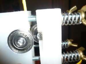
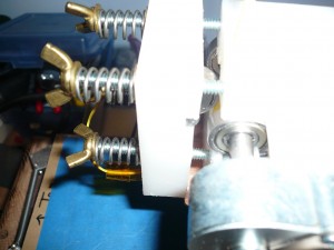
Some detail pictures of the exturder body.
