I thought the firmware I’ve been using had PID temperature control, but it turns out it was using a simple on/off thermostat routine that caused the extruder temperature to have big variations.

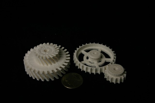
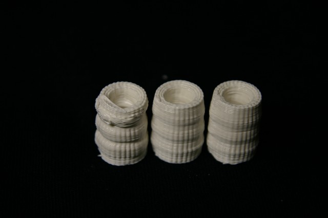
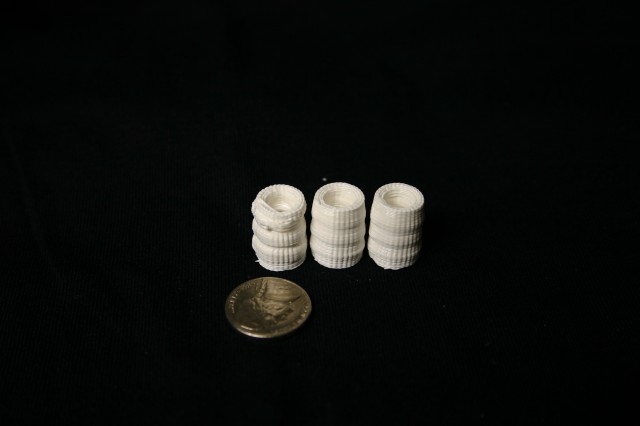
Here are some prints of a RepRap Mendel part, basically a small cylinder. Due to the small size of the part quality really suffers as the temperature swings up & down.

The cylinder on the left was printed with the simple On/Off temperature control, and the two on the right were printed with a On / Medium control, that instead of turning the heater entirely off when the temperature exceeded it’s set limit, just set the heater to a medium value. It’s not a real fix, but it was simple to implement, and still makes a pretty significant difference.

Worse, bad, bad.

The right-most part in this picture will probably be usable, but just barely.

Left = bad.

Here are some larger parts that show the effect in the ‘banding’ you see every couple of layers, and the lower layers that are %100 solid internally, are a bit wider, which they should not be.

Notice the horizontal banding.

The code I changed isn’t *much* better, but it helps some, if you’re using the tonok-MMM firmware fork look at the file Tonokip_Firmware.pde in the manage_heater() function:


The original code was this:

if(current_raw >= target_raw) digitalWrite(HEATER_0_PIN,LOW);
else digitalWrite(HEATER_0_PIN,HIGH);

and I replaced it with this:

if (target_raw <= 50) {
analogWrite(HEATER_0_PIN,HEATER_0_OFF);
} else {
if(current_raw >= target_raw) {
analogWrite(HEATER_0_PIN,HEATER_0_LOW);
} else {
analogWrite(HEATER_0_PIN, HEATER_0_HIGH);
}

and added these lines to configuration.h:

const char HEATER_0_LOW = 85;
const char HEATER_0_HIGH = 255;
const char HEATER_0_OFF = 0;

The HEATER_0_LOW value should be a number in the 0-255 range that allows your heater to cool from your usual print temperature, be careful not to set it too high, or your nozzle will never cool down. As mine sits now it will idle at about 165C when the heater is on ‘Low’.
I’ve managed to connect a webcam to the ArduinoMega that is controlling my 3D printer, so now I can trigger a picture from the G-code that the printer is reading to make the part.

This means I can take a picture at the beginning of each printed layer, and make time-lapse video like this:

The RepRap is a 3D printer that builds small objects out of plastics, by squirting layers of melted plastic out of a nozzle, on to a computer-controlled moving platform. Once a single layer is made, it moves to the next layer up from the bottom, repeating this process until your object is created.
This process is called “Fused Deposition Modeling”, or “Fused Filament Fabrication”.

The end result is a strong plastic part, with a slightly ridged surface.

This is basically the same method used by the Stratasys FDM rapid prototyping machine, which costs around $30,000.

The Chicken & Egg problem of building a RepRap machine is that many of the parts are actually made using a RepRap, so if you don’t already have access to one, you’re at a disadvantage.

I’ve been working on what’s called a RepStrap, that is, it’s not exactly following the plans for a RepRap machine, but can be used to ‘bootstrap’ construction of a RepRap. The end result is the same in that you have a 3D printer, but the construction plans & materials differ.

When starting my build I had a few design goals: appearance, cost, and functionality.

Read the rest of this entry »

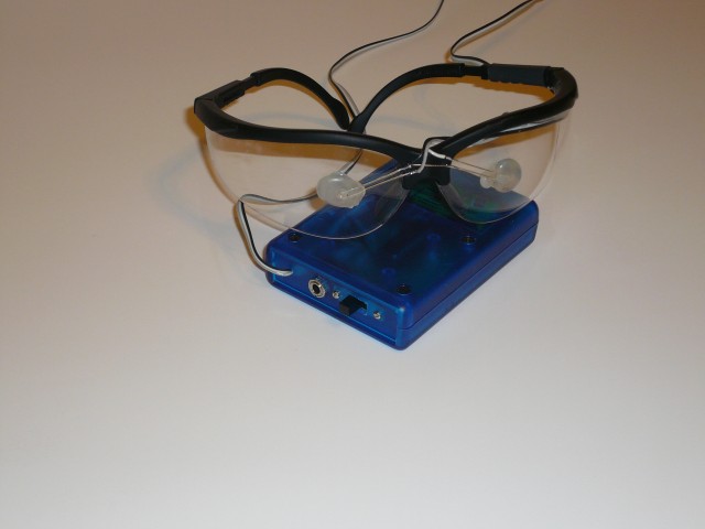
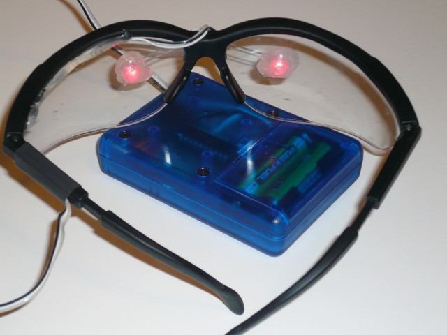
This is my own version of the “Brain Machine” as published in Make Magazine vol 10.

Basicially the combination of flashing lights in your eyes, and playing binaural beats into your ears is supposed to entrain your brainwaves to those of a relaxed state, leaving you feeling mellow and rested. I can’t really describe exactly what it’s like, but it’s not just snake-oil.

The project as described in make uses a repurposed mini-POV kit, with replacement firmware. I already had some
atmega-48 chips and a programmer, so I just built it on a small piece of perf-board.

The case is a small project case I had in my box ‘o parts, the frame is just a pair of safety glasses, the LED’s are held in place with hot-glue, which also diffuses the light.

I’m pleased with the end result, overall a fun evening project.

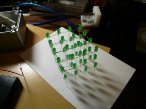
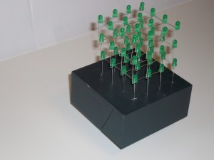
This is a 4 * 4 * 3 cube of green LEDs that displays a few pretty patterns,  in random order.  It’s driven by a Atmel AVR chip, and 2 8-bit shift registers.

Each horizontal level is wired to the shift registers,  so an entire level can be lit at once,  and the levels are each lit in sequence, fast enough that it appears as if all the levels are lit at once.

The code is in C, compiled with GCC-AVR.  The base is a plastic Dysan 3.5 floppy disk box.

Video of the animations:
ledcube01