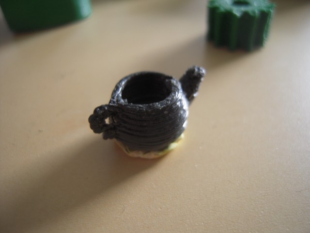
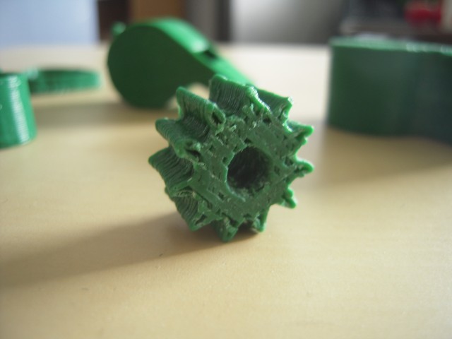
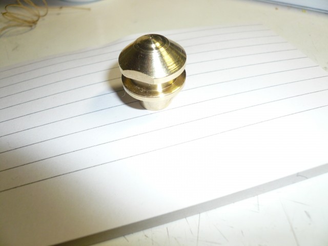
Here’s a few objects I’ve printed. They came out mostly Ok, but I think I have a lot of tuning to do in Skeinforge, the software that generates the actual printing instructions. All the objects have been cleaned up with a razor, as there were some strings.
The RepRap is a 3D printer that builds small objects out of plastics, by squirting layers of melted plastic out of a nozzle, on to a computer-controlled moving platform. Once a single layer is made, it moves to the next layer up from the bottom, repeating this process until your object is created.
This process is called “Fused Deposition Modeling”, or “Fused Filament Fabrication”.
The end result is a strong plastic part, with a slightly ridged surface.
This is basically the same method used by the Stratasys FDM rapid prototyping machine, which costs around $30,000.
The Chicken & Egg problem of building a RepRap machine is that many of the parts are actually made using a RepRap, so if you don’t already have access to one, you’re at a disadvantage.
I’ve been working on what’s called a RepStrap, that is, it’s not exactly following the plans for a RepRap machine, but can be used to ‘bootstrap’ construction of a RepRap. The end result is the same in that you have a 3D printer, but the construction plans & materials differ.
When starting my build I had a few design goals: appearance, cost, and functionality.
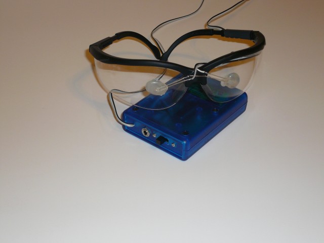
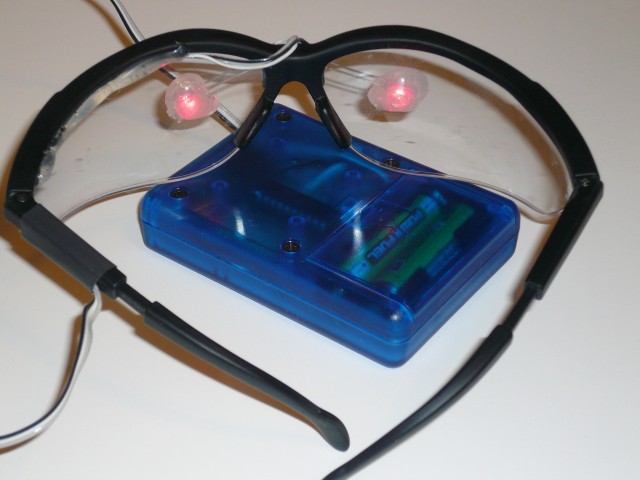
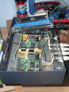
This is my own version of the “Brain Machine” as published in Make Magazine vol 10.
Basicially the combination of flashing lights in your eyes, and playing binaural beats into your ears is supposed to entrain your brainwaves to those of a relaxed state, leaving you feeling mellow and rested. I can’t really describe exactly what it’s like, but it’s not just snake-oil.
The project as described in make uses a repurposed mini-POV kit, with replacement firmware. I already had some
atmega-48 chips and a programmer, so I just built it on a small piece of perf-board.
The case is a small project case I had in my box ‘o parts, the frame is just a pair of safety glasses, the LED’s are held in place with hot-glue, which also diffuses the light.
I’m pleased with the end result, overall a fun evening project.
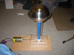
This is Van de Graff machine I built in 2006. It’s made of some plexiglass tube, and two mixing bowls.
The rollers are Delrin and teflon, as you want to use materials from opposite ends of the triboelectric scale.
The base is 1/2″ plastic that I heated with a torch and bent,
The rollers and the roller-support pieces were turned on my mini-lathe.
The axles are made of 8mm drill rod turning in skate bearings.
The belt is made from a piece of Theraband, basically a big sheet of rubber used for exercise. It’s glued into a loop with contact cement.
The motor is a surplus DC motor, powered by a 24v DC power supply. I think the power supply was originally for some part of a phone system, I picked it up at a local freight-salvage store.
I put an AC light dimmer inline to adjust the input power to the AC-adapter, which works pretty well to adjust the motor speed.
One problem I did run into was that all the static building up would cause arcing within the power supply, so I broke it open and insulated everything with silicone caulking. Probably not the best thing for the cooling, but I never really run it for more than a few minutes at a time, so I haven’t had any problems.
I built a mounting for the motor and speed control, but I don’t have any pictures of it, hopefully I’ll remember to take some.
Here’s a few pictures.
Here’s a picture of some sparks, this was a 15 second exposure, and the sparks arc up to two inches when it’s runnning well.
Things that affect how well it works are mostly humidity, and how clean the ‘sphere’ is. Any dust causes sharp points where the electrons will ‘leak’ off, so for best results I’ll wipe it down first with some alcohol and a lint-free microfiber cloth, Supposedly it also helps to cook off any moisture by using a hair dryer, but I’ve never bothered to try that.
One more picture.
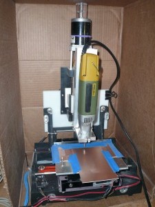
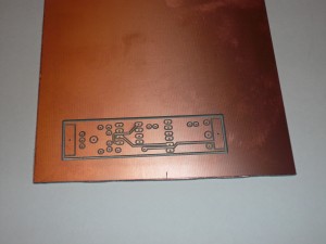
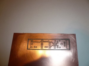
Last week I did a test pcb milling on my cnc pcb mill. I’m still learning how to properly configure the PCB-Gcode software, and I think this is the best result to date.
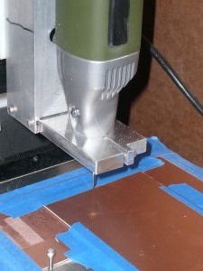
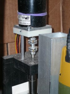
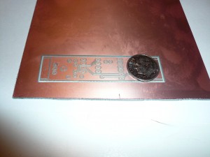
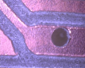
The board is the top side of LadyAda’s Drawdio board, and it took about 15 minutes to mill. I used a 60 degree pcb bit I got from a Chinese seller on eBay. Before drilling the holes I ran through the drilling gcode, once with the pcb bit still in the spindle, at a higher depth. Basicialy this drills shallow pilot holes through the copper, but not through the PCB. This helps reduce the amount of “walking” that the tiny drill bit does when it’s drilling the holes.
The holes are still off-center a bit from the pads, I’m still trying to figure out why that is. One possibility is that I accidentally twisted the router in it’s mounting when I changed from the pcb bit to the drill bit.
One more picture, after a little cleanup with some 1500 grit sandpaper, I think it came out pretty well.
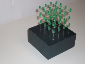
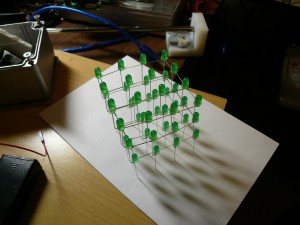
This is a 4 * 4 * 3 cube of green LEDs that displays a few pretty patterns, in random order. It’s driven by a Atmel AVR chip, and 2 8-bit shift registers.
Each horizontal level is wired to the shift registers, so an entire level can be lit at once, and the levels are each lit in sequence, fast enough that it appears as if all the levels are lit at once.
The code is in C, compiled with GCC-AVR. The base is a plastic Dysan 3.5 floppy disk box.
Video of the animations:
ledcube01
I’m putting up these new pages to document my hobby projects, hopefully some will be interestng. I’ve got a few already finished things to post.
I’m not usually very meticulous about documenting things, or even taking pictures, so many enties may be pretty spotty. If I’ve left out any details, feel free to drop me an email with any questions.
