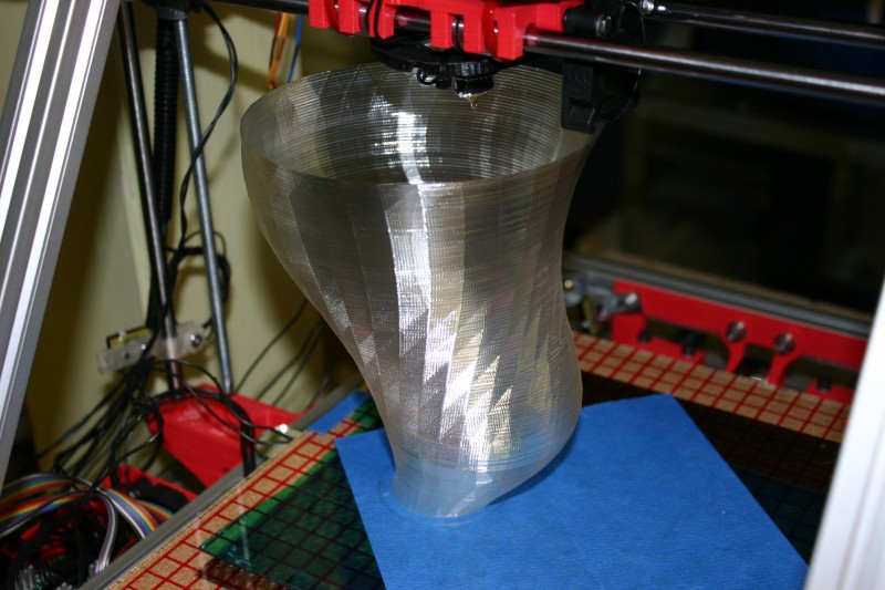
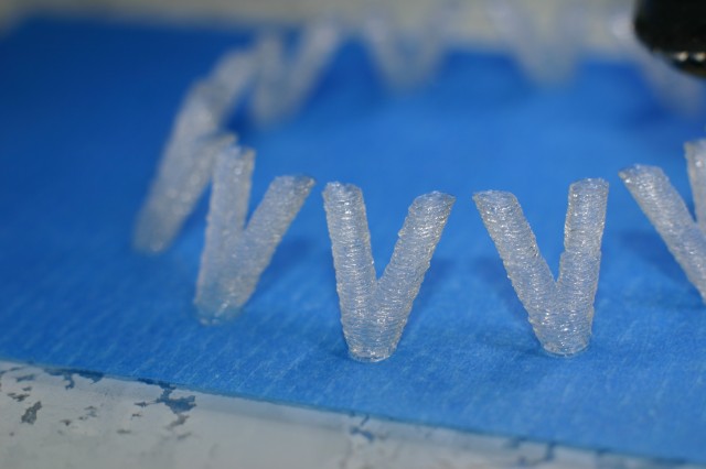
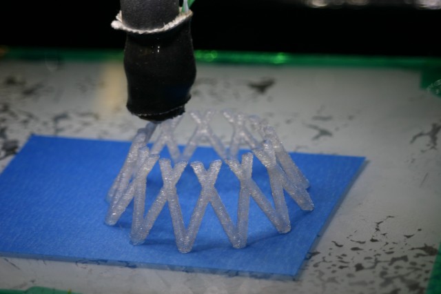
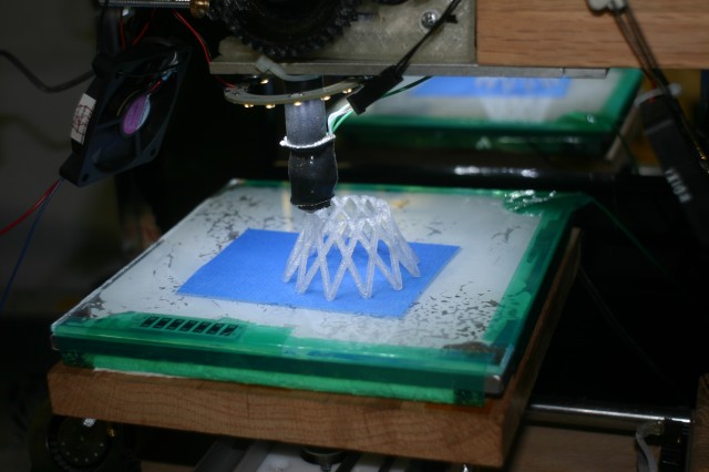
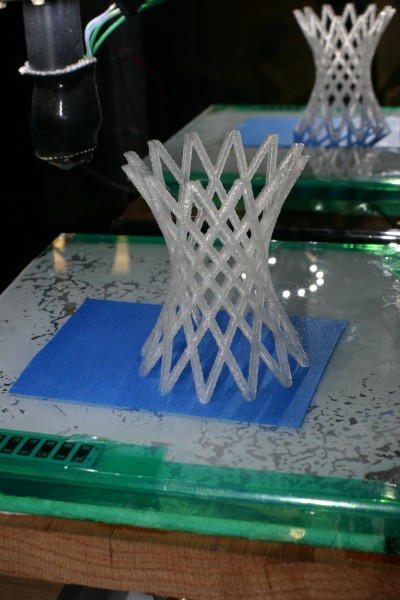
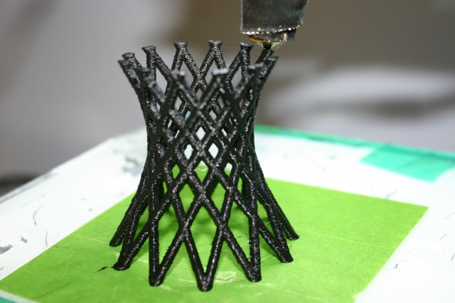
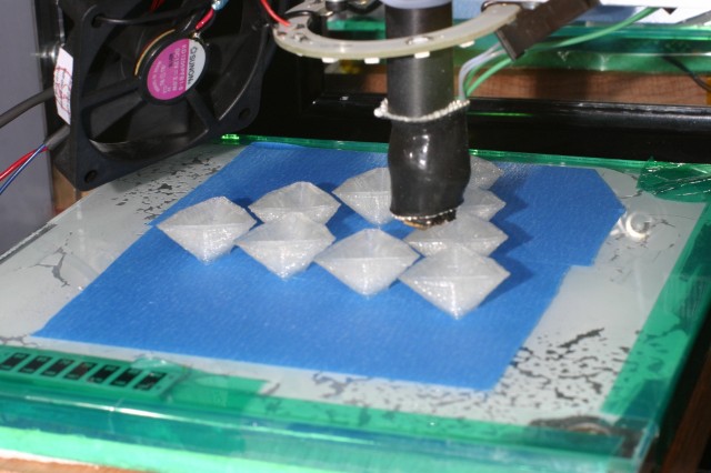
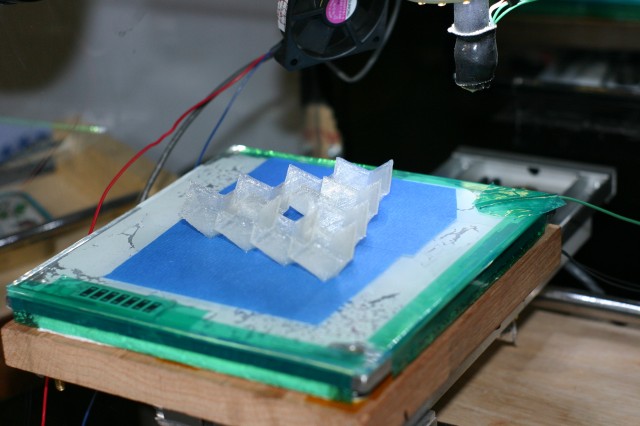
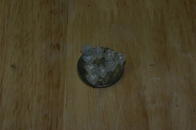
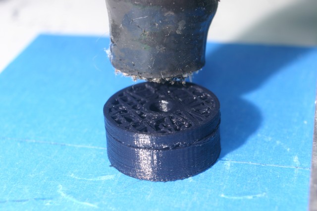
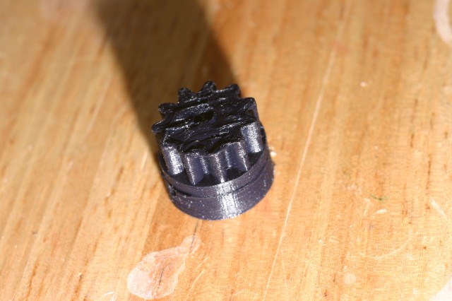
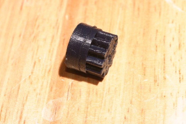
Single walled print at 0.17mm layers, with a 0.25mm nozzle on a MakerGear hotend.
Slic3r gcode parameters are after the pictures.


; generated by Slic3r 0.7.2b on 2012-05-06 at 01:09:14
; layer_height = 0.18
; perimeters = 1
; solid_layers = 4
; fill_density = 0
; nozzle_diameter = 0.25
; filament_diameter = 1.73
; extrusion_multiplier = 1
; perimeter_speed = 45
; infill_speed = 80
; travel_speed = 100
; extrusion_width_ratio = 0
; scale = 1
; single wall width = 0.28mm

I recently switched to the Kliment fork of the TonokIP fork of the Hydra-MMM firmware.

The tiny pauses between g-code segments are all but gone, and I’ve been re-printing some things
to do before & after comparisons.

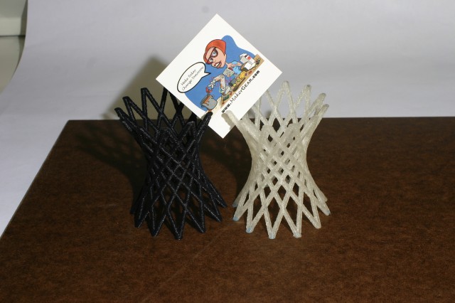
The black PLA-4043D Hyperboloid was printed with the Tonokip firmware, and the recent natural 4043D PLA was printed with the Kliment firmware.
Both were printed through a MakerGear plastruder with a 0.35mm nozzle, at 0.25mm layer heights. I’ve been using the same hot-end for a while now, and have put nearly 15lbs of PLA through it. The took 2 hours each, give or take a few minutes.

Hopefully my picture managed to capture the difference in surface quality. Hit the full-size photos to see it better.

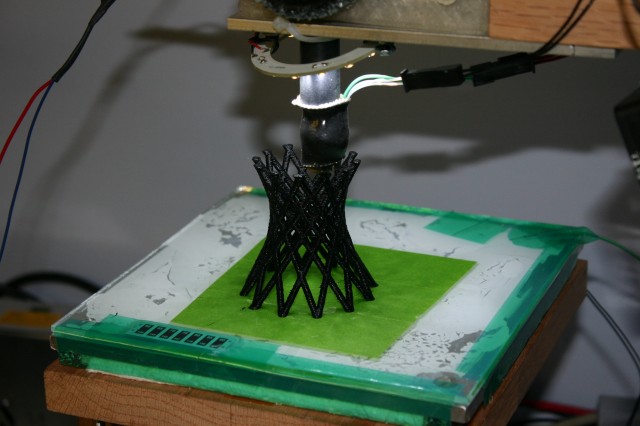
Just few minutes in

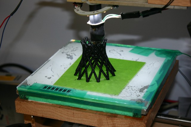
About 25% done

Finished print, unretouched photo. :-)

Left is tonokip, right is Klimentip.

Print of George Hart’s hyperboloid model from http://www.georgehart.com/rp/makerbot/makerbot.html


Penrose Triangle in progress

Done.

Trial run, at %25 size

I did a test print at 0.08mm layers, the smallest layer height I’ve attempted yet.

I used a Makergear Plastruder, and black Ultimachine 4043D PLA.

Skeinforge sliced it onto 187 layers. It was not a fast print, taking about 2.5 hours.
Aside from a kind of smeary top layer, it came out ok.
Pictures follow:

0.08mm Nophead pulley in progress.

0.08mm layers

No manual cleanup done yet.

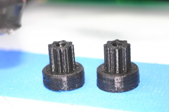
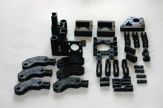
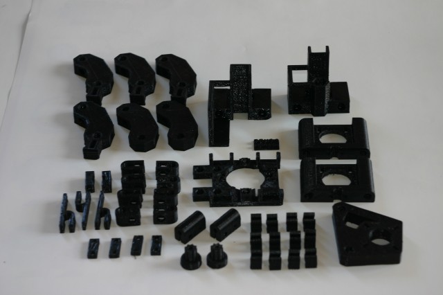
These two pulleys are the final print of a complete Prusa Mendel parts set I’ve been printing for a friend. It took about 3 weeks of evenings on & off. Most of the parts were printed one at a time, I didn’t use the production parts files.

The parts are now in the hands of Eric, hopefully he’ll be printing in a month or so.

Here’s some pictures.

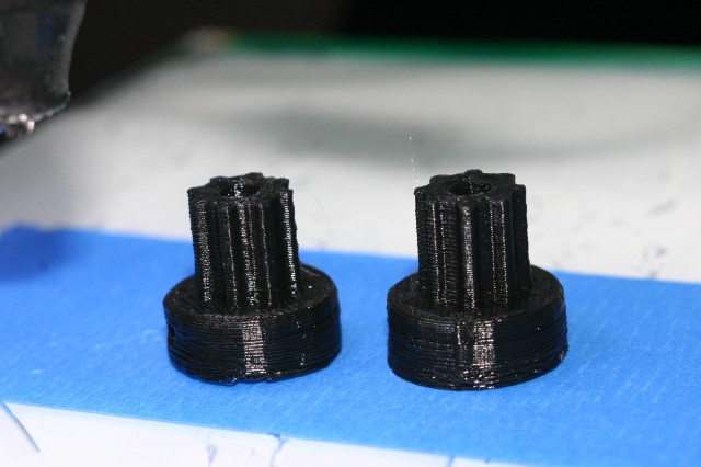
Pair of Printed PLA Prusa Pulleys

Done!

It's like a quarter of a Mendel set.

Those spans are magic!

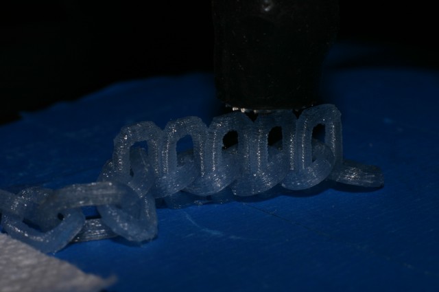
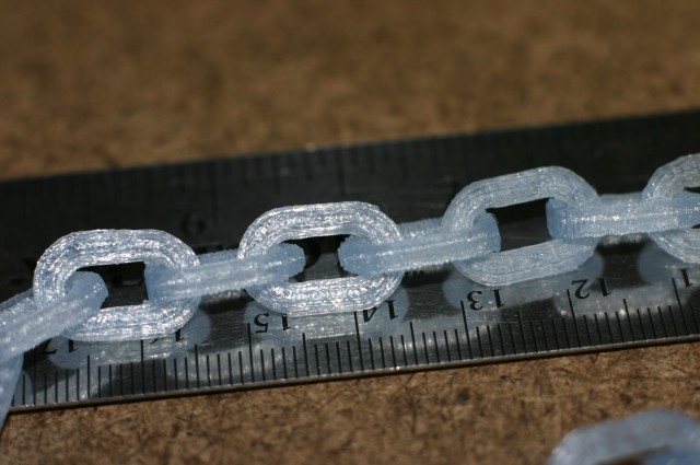
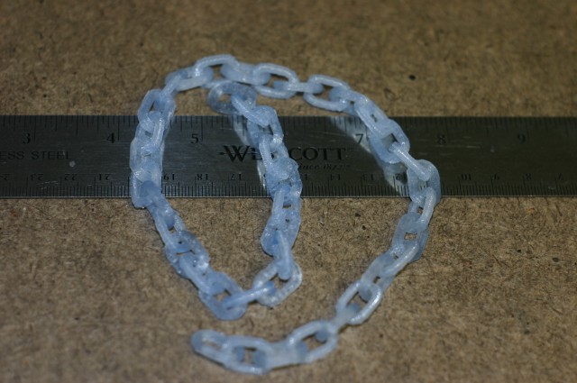
I made some links of chain, arranged just so that I could slip a previously printed link over two adjacent links, while they were still being printed. Purists may take exception, but I think it’s kind of cool.

The links were printed with a 0.4mm MakerGear nozzle, using 0.26mm layers. All the ‘extra shells’ settings in Skeinforge->Fill set to 0, the infill turned way down, and lots of cool air..

Almost done printing

Each link is about 10mm * 15mm

41 links, printed in batches of 5.

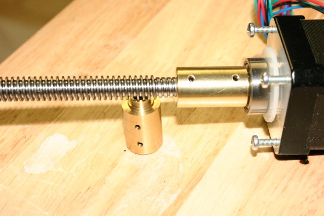
I made a new Z-axis motor coupler, as I suspect the old one was slightly off-center & causing wobbles to show in printed parts. The new one seems better, but I still have a little bit of wobble from a still undetermined source.

new Z axis shaft coupler

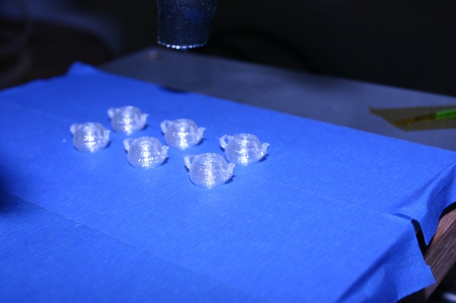
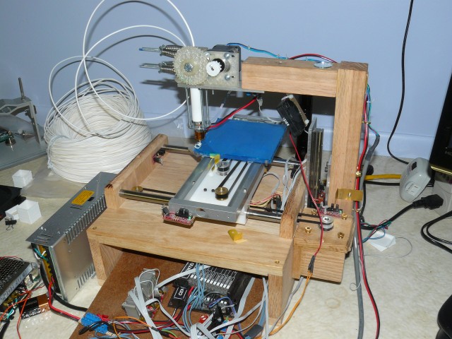
Here are a few recent prints. I recently started using the “Dimension” module within Skeinforge to retract the feed-stock between moves, and it’s really helped reduce the “stringies” that’d happen between parts.

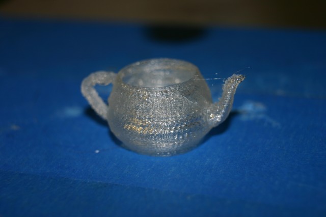
I'm six little teapots.

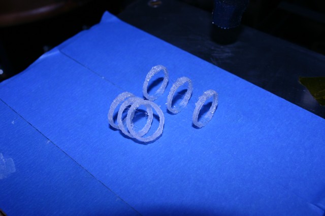
These rings printed fine, but a few lost their grip right as the print finished.

Vertical rings

Hot off the printner, no cleanup done

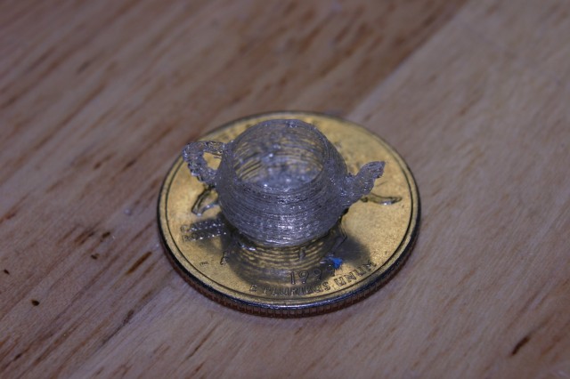
teapot on a US quarter, for scale.

I thought the firmware I’ve been using had PID temperature control, but it turns out it was using a simple on/off thermostat routine that caused the extruder temperature to have big variations.

Here are some prints of a RepRap Mendel part, basically a small cylinder. Due to the small size of the part quality really suffers as the temperature swings up & down.

The cylinder on the left was printed with the simple On/Off temperature control, and the two on the right were printed with a On / Medium control, that instead of turning the heater entirely off when the temperature exceeded it’s set limit, just set the heater to a medium value. It’s not a real fix, but it was simple to implement, and still makes a pretty significant difference.
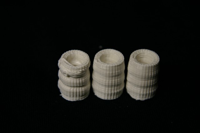
Worse, bad, bad.

The right-most part in this picture will probably be usable, but just barely.
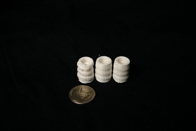
Left = bad.

Here are some larger parts that show the effect in the ‘banding’ you see every couple of layers, and the lower layers that are %100 solid internally, are a bit wider, which they should not be.
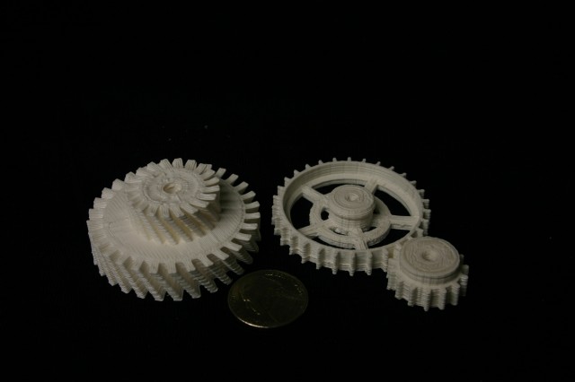
Notice the horizontal banding.

The code I changed isn’t *much* better, but it helps some, if you’re using the tonok-MMM firmware fork look at the file Tonokip_Firmware.pde in the manage_heater() function:


The original code was this:

if(current_raw >= target_raw) digitalWrite(HEATER_0_PIN,LOW);
else digitalWrite(HEATER_0_PIN,HIGH);

and I replaced it with this:

if (target_raw <= 50) {
analogWrite(HEATER_0_PIN,HEATER_0_OFF);
} else {
if(current_raw >= target_raw) {
analogWrite(HEATER_0_PIN,HEATER_0_LOW);
} else {
analogWrite(HEATER_0_PIN, HEATER_0_HIGH);
}

and added these lines to configuration.h:

const char HEATER_0_LOW = 85;
const char HEATER_0_HIGH = 255;
const char HEATER_0_OFF = 0;

The HEATER_0_LOW value should be a number in the 0-255 range that allows your heater to cool from your usual print temperature, be careful not to set it too high, or your nozzle will never cool down. As mine sits now it will idle at about 165C when the heater is on ‘Low’.
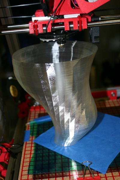
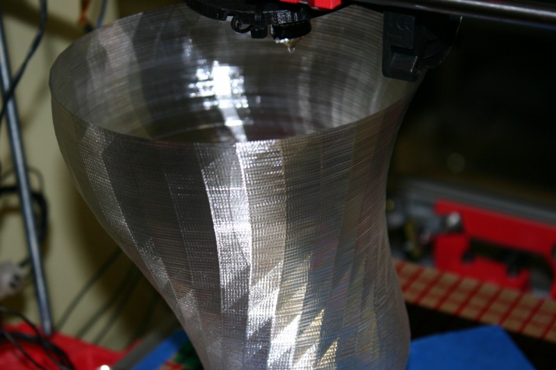
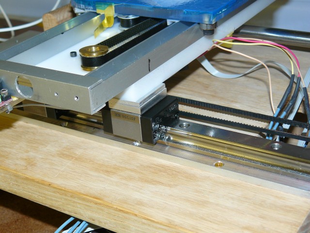
I’ve replaced my X axis, which was bronze bushings sliding on steel rod, with a recirculating-ball linear bearings and guide. The former X axis had enough play in it that you could feel it just by wiggling the print bed, and was affecting print quality quite a bit.

Between my new extruder hot-end, this new bearing, and lowering layer height to 0.36mm, I’m getting print quality that’s better than anything I’ve produced to date.

It’s also faster, so much faster that I’ve had the motor miss a few steps. I’m experimenting with feeding 24 volt power to the stepper motor drivers, and initial results seem good, although everything runs a bit warmer. I also have another linear bearing, and may use it on the Y axis.

Here’s a “before” picture of my previous X axis slide:

Bronze bushings sliding on steel rod.

And here’s a picture of the new linear bearing & rail:

Recirculating-ball linear carriage & rail

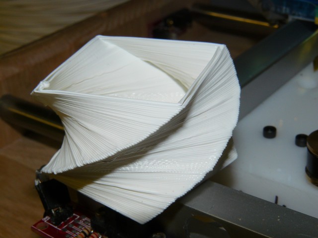
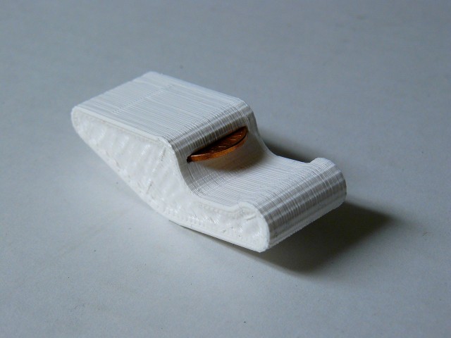
Here’s some of the first test prints I did with the new bearing:

Twist-cube, printed with new X axis linear bearing

A one-cent bottle opener

Here is some video of it in action, if you listen carefully you can hear the *tick* *tick* *tick* *tick* of the ball-bearings clicking around their recirculating channels inside the carriage.