For years and years I’ve been facinated with CNC machinery. There’s something incredibly compelling about the idea that you can design something digitally, with all the “undo” you want, and then have a machine make it for you.

Of course, it’s really not that simple in practice, but it’s still an incredibly exciting thing.

For a couple of years now I’ve been picking up motion control parts whenever I see them available cheaply, even if I didn’t have a particular need for them, yet.

Mid-summer 2009 I found a surplus X/Y table on eBay, put in a minimum bid of $50, and won.

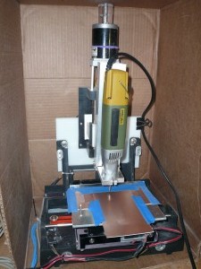
This gave me a pretty good starting point for a light-duty milling machine, I had two axis’s that were more accurate than I’d be able to make myself, with 2 stepper motors. I already had a few stepper motor drivers.

I built a ‘Z’ axis that used bronze bushings sliding on steel rods, driven by 10TPI acme threaded rod. The lead-nut was a chunk of Acetal plastic that I’d tapped threads into using a home made tap.

The first revision used a Bosch Colt 1.0HP router for the spindle, as I’d read online that they had very low runout(ie: wobble) in the spindle. I’d measured the Bosch’s runout at about 0.0035″, which seems pretty good for a consumer grade router.

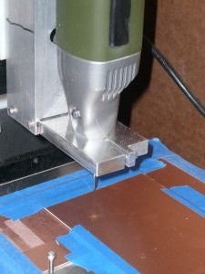
After making a few circuit boards I realized that I’d need something even smoother, and after a little deliberation I ordered a Proxxon IB/E rotary tool. It was $110, which is a lot to pay for what’s essentially a Dremel(which would have been about 1/2 the price).

Once the Proxxon arrived all my hesitations vanished, I can’t speak highly enough about it. I measured the spindle runout at about 0.0005″. I can turn it all the way up to 20,000 RPM and put it down on the desk, and it just sits there. A Dremel would vibrate itself off the edge of the table within a few seconds. Also, even at full speed, it’s quiet enough that I can run it at night while everyone is asleep. The Bosch was loud enough that I didn’t even like to be in the same room with it.

I was incredibly lax about taking pictures of the build process, but did manage to snap a few after it was done. Please ignore the cardboard-box-dust-suppressor system, I haven’t had time to make a proper box.


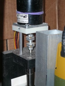
A proper shaft coupler handles small misalignments:
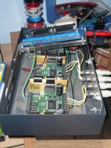
Repurposed ps2 keyboard cables used for the motors:

Little video of it in action:

CNC mill test from bill S on Vimeo.
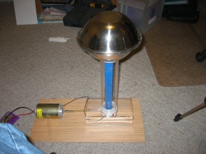
This is Van de Graff machine I built in 2006. It’s made of some plexiglass tube, and two mixing bowls.

The rollers are Delrin and teflon, as you want to use materials from opposite ends of the triboelectric scale.

The base is 1/2″ plastic that I heated with a torch and bent,

The rollers and the roller-support pieces were turned on my mini-lathe.

The axles are made of 8mm drill rod turning in skate bearings.

The belt is made from a piece of Theraband, basically a big sheet of rubber used for exercise. It’s glued into a loop with contact cement.

The motor is a surplus DC motor, powered by a 24v DC power supply. I think the power supply was originally for some part of a phone system, I picked it up at a local freight-salvage store.

I put an AC light dimmer inline to adjust the input power to the AC-adapter, which works pretty well to adjust the motor speed.

One problem I did run into was that all the static building up would cause arcing within the power supply, so I broke it open and insulated everything with silicone caulking. Probably not the best thing for the cooling, but I never really run it for more than a few minutes at a time, so I haven’t had any problems.

I built a mounting for the motor and speed control, but I don’t have any pictures of it, hopefully I’ll remember to take some.

Here’s a few pictures.

my Van de Graff generator, made from some junk I had.

Here’s a picture of some sparks, this was a 15 second exposure, and the sparks arc up to two inches when it’s runnning well.

Long-exposure pic of Van de Graff discharges

Things that affect how well it works are mostly humidity, and how clean the ‘sphere’ is. Any dust causes sharp points where the electrons will ‘leak’ off, so for best results I’ll wipe it down first with some alcohol and a lint-free microfiber cloth, Supposedly it also helps to cook off any moisture by using a hair dryer, but I’ve never bothered to try that.

One more picture.

static electricity is hard to photograph

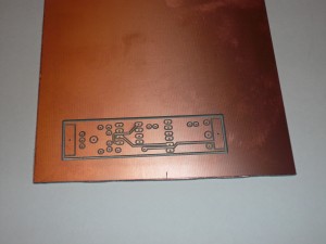
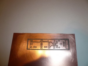
Last week I did a test pcb milling on my cnc pcb mill. I’m still learning how to properly configure the PCB-Gcode software, and I think this is the best result to date.

The board is the top side of LadyAda’s Drawdio board, and it took about 15 minutes to mill. I used a 60 degree pcb bit I got from a Chinese seller on eBay. Before drilling the holes I ran through the drilling gcode, once with the pcb bit still in the spindle, at a higher depth. Basicialy this drills shallow pilot holes through the copper, but not through the PCB. This helps reduce the amount of “walking” that the tiny drill bit does when it’s drilling the holes.

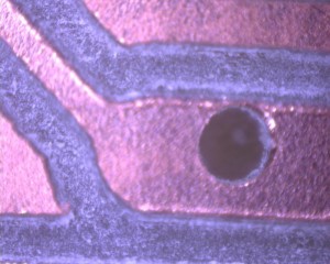
The holes are still off-center a bit from the pads, I’m still trying to figure out why that is. One possibility is that I accidentally twisted the router in it’s mounting when I changed from the pcb bit to the drill bit.


test

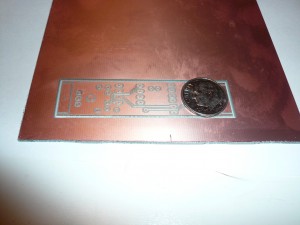
Milled pcb, with a dime for scale.

pcb pad/hole alignment at 100x magnification.

One more picture, after a little cleanup with some 1500 grit sandpaper, I think it came out pretty well.

after some cleanup with 1500 grit sandpaper.