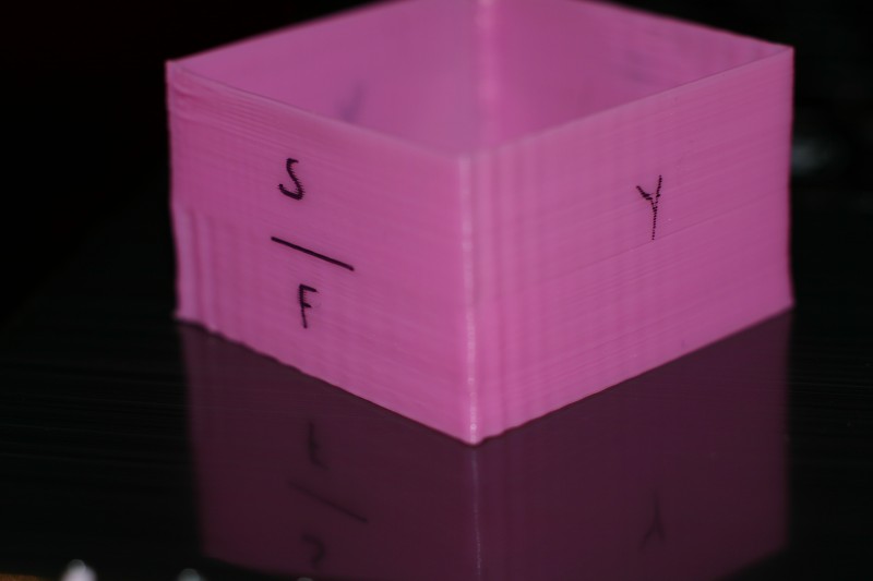
I spent some time printing several test parts, trying to determine the source of some of the ripples that may appear after a sharp corner in a print. Firmware settings were tweaked to aggravate the problem, raising the “jerk” value high enough to disable acceleration.
This print was done from manually generated gcode. The part labeled “f” was printed faster than the other sides, and the part labeled “s” was printed at a slower speed.
Until now I’d always thought that corner ripples were caused by the axis which just stopped moving taking a moment to quit vibrating, If that was the case I would expect the patterns on the side labeled “y” to vary with the speed of the previous move.
It appears that the waves are actually caused by movement in the axis that’s just starting to move.
I repeated this test on the other axis, and the results were similar.
If anyone has ideas on this, please let me know.

What’s happening is that the belts are stretching, and so when the axis stops suddenly (like on the corner) the belt stretches and causes the axis to bounce, which is what you see as ripples. Slowing down eliminates this, as does making the acceleration slower so the transition is less harsh. There are other things you can do too, like tightening the belts (if they’re loose) or switching to reinforced belts that stretch less. Personally, I would slow down the acceleration.
I hope that’s useful.
That’s what I thought too, before I did these tests. If that were the case I would expect the ripples on the “Y” side to vary, based on the speed of the previous move.